|
Frodo - a 10 inch travel Dobson10 inch, f/4.8 newtonian |
|
Web Ring |
|
Next |
Previous |
Random |
List Sites Next 5 | Previous 5 | Join |
|
|
|
|
|
optics hogging out smoothing the curve polishing foucault tester figuring silvering |
|
|
|
mechanics mirror cell wire spider focuser middle ring rocker box |
|
|
|
|
basic considerations |
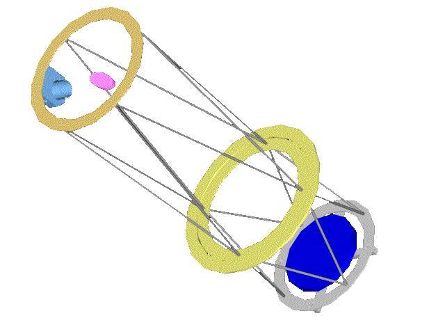
| Building a travel Dobson usually means going for lightness. Ive thought about my habits and preferences and realized, I much more like to be able to watch the skies comfortably (couch potato that I am) than to take my telescope on a bicycle through the alps, set it up in 2 minutes and lie down for altitudes less than 20°. I want to use 2 inch eyepieces and have all the comfort of a homebound telescope. But still I wanted the telescope portable because when I travel with my family I thought it would be nice to have a telescope I can take along, set up once at our destination and take apart at the end of the holiday. It must be air travel compatible. For comfort of viewing the traditional Dobson design with a fairly high centre of gravity resulting in a tall rockerbox really appealed to me. It means when watching the skies the eyepiece moves on a hemisphere with an elevation equal to the height of the rotational axis and a diameter equal to the distance of the eyepiece from that axis. The closer that COG is to the eyepiece, the smaller the hemisphere and the less I would have to move to jump from object to object. Even more comfortable is to be able to rotate the tube assembly along its long axis for easiest viewing position. This is usually realized with a tube in a rotation mounting cradle. I didnt want a solid tube because that would be way too bulky to take along so it had to be a truss tube design. On the internet I came across the very nice homepage of Steven Lee and his explanation on why most Serrurier truss telescopes really are not what they call themselves. It is the back to back arrangement of the triangular trusses connecting the upper tube assembly including secondary & focuser and the lower tube assembly including mirror and cell with a central element that is connected to the support, that makes a genuine serrurier truss. The ingenious principle makes sure the optics stay aligned even though the secondary and the main mirror sag when going from high to low altitudes by making sure they sag the same amount. The idea of a three ring construction formed and I thought it would solve a lot of the construction problems and provide the functionality I wanted. This is the design I came up with: |
 |
|
The single upper ring with a wire spider and a self-made low profile 2 inch Crayford focuser is connected to a flexible birch plywood ring (9mm), which in turn is supported by a stronger plywood ring (19mm) which provides the necessary rigidness and attaches to the altitude bearings (not shown). The flexible ring can rotate inside this ring. The 6 point mirror cell (calculated with PLOP) is made from aluminium square tubing (20mm) and for easier collimation provides four connections to the lower plywood ring. This design is strongly influenced by Steven Lees wonderful 12 inch scope. The collimation thumbscrews face upwards and are easily accessibly. Since the focuser and the collimations screws align, it is very easy to collimate. One knows exactly which screw has to be turned to tune the alignment. This principle also applies to the wire spider. If my thinking was right the overall design should provide the following advantages:
- I am free to choose the centre of rotation, I can even add weight to the upper ring to get nice comfortable mechanical viewing characteristics. - the ability to rotate the OTA along the longitudinal axis always provides a comfortable eyepiece position for relaxed viewing. No need to bring along an adjustable viewing chair, any chair will do. - the maximum truss length is smaller, for a travel scope this means less bulky. - the smaller truss length results in a higher resonance frequency of the tube assembly, the scope hopefully should not suffer from vibration problems at higher magnifications. - the construction from flat rings can be collapsed into a low volume, low bulk travel form. - the truss tubes diameters and connections can be chosen to equal the amount of sag for the upper ring and lower ring, a very forgiving design if your connections are not very rigid. |
 |
|
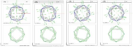
To match the sag of the upper and lower ring I found it best to use 15 mm diameter aluminium trusses (2 mm wall thickness) for the UTA and 10 mm diameter (1 mm wall thickness) for the LTA. This calculation is based on the assumption of ideal truss connections and yields sag of not more than 0.03 mm at both ends (with the telescope pointing at 0° altitude and different rotation angles around the lateral telescope axis). These results made me realize the sag caused by the static loads on the truss construction is so small, that it is unnecessary sophistication to choose different tube diameters and wall thickness. I bought readily available standard aluminium tubing from the DIY store with 15 mm diameter and 1 mm wall thickness. Recalculation with these values gave me maximum sag of 0.05 mm at the upper end and 0.01 mm at the lower end, so taking the telescope from 90 deg alt to 0 deg will result in a parallel misalignment of 0.04 mm, which I hope to find acceptable. Other effects like the imperfect real world truss connections that I can realize with my handheld DIY tools will dominate the amount of sag. Still I hope that by using this kind of construction the unavoidable imprecision in construction will cancel each other out. |
|
![]()
© 2005 by Andreas Derwahl • contact